PRO-HC - Install Guide
PRO-HC - Mounting Controller
INSTALLING THE PRO-HC CONTROLLER
Start by choosing a location with good Wi-Fi coverage. Wi-Fi coverage can be easily tested using a smartphone. A high signal strength is recommended. Wi-Fi connectivity can also be tested on the Pro-HC itself (signal strength is shown when you select a wireless network).
MOUNTING THE CONTROLLER TO A WALL
All necessary hardware is included for most installations.
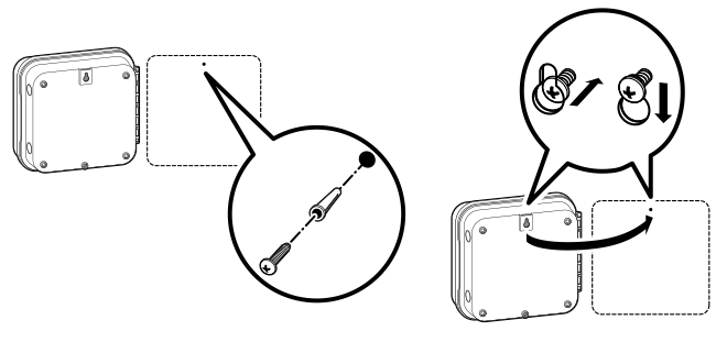
- Use the hole at the top of the controller as a reference and secure a 1" (25 mm) screw into the wall. Note: Install screw anchors when attaching the controller to drywall or masonry wall.
- Align controller with the screw and slide the keyhole on top of the controller over the screw.
- Secure controller in place by installing screws in the other mounting holes.
| STEPS 1-3 |
 |
PRO-HC - Connecting AC Power
| Indoor Cabinet: |
- Route transformer cable through the hole on the bottom left side of the controller
- Connect one Yellow Wire to each of the screws marked 24AC and the Green Wire to GND.
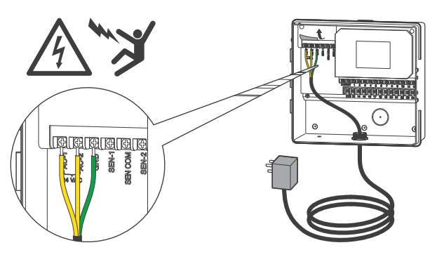
Note: The indoor Pro-HC is not water or weather-resistant and must be installed indoors or in a protected area. This device is not intended for use by young children. Never let children play with this device.
| Outdoor Cabinet: |
The outdoor model is water and weather-resistant. Connecting the outdoor Pro-HC to the primary power should be done by a licensed electrician following all local codes.
- Route AC power cable and conduit through the 1/2" (13 mm ) conduit opening on the left side of the bottom of the cabinet.
- Connect the wires to the transformer wire located inside the junction box. International units are supplied with a built-in terminal strip. Always use a UL-listed conduit 1/2" (13 mm ) male adapter when installing the AC wiring.
- Insert the adapter into the 1/2" (13 mm ) hole at the bottom of the controller. Attach a nut to the adapter inside the enclosure.
- A battery is not required for this controller. Watering will not occur without AC power. Since this controller has non-volatile memory, the program, clock, and calendar will be retained during a power outage.
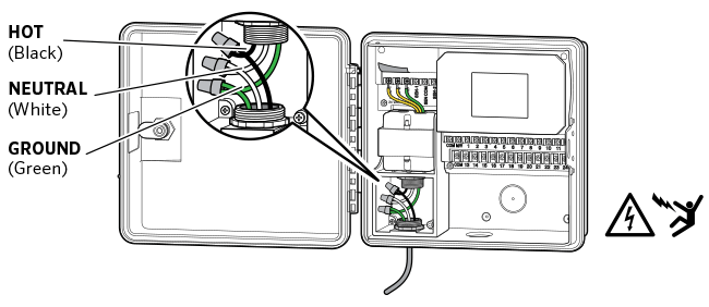
Note: To be performed by a licensed electrician only. Always use UL listed ½" (13 mm) conduit with male adapter when installing AC wiring. Pro-HC controllers are intended to be supplied AC power with an over-current protected device. Improper installation could result in shock or fire hazard. This device is not intended for use by young children. Never let children play with this device.
PRO-HC - Connecting Solenoid Valves
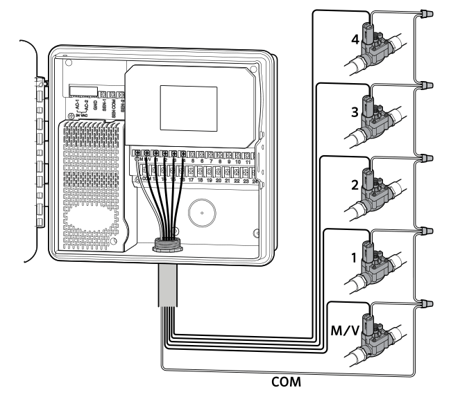
- Route valve wires between control valve location and controller.
- At the valve location, attach a common wire to either solenoid wire of all valves. The most commonly used color for the common wire is white. Attach a separate control wire to the remaining wire of each valve. All wire splice connections should be done using waterproof connectors.
- Route valve wires through the conduit and attach conduit to one of the openings on the bottom of the cabinet.
- Strip 1/2" (13 mm) of insulation from ends of all wires. Secure the valve common wire to "COM" (Common) terminal. Attach all individual valve control wires to the appropriate station terminals.
| PRO-HC CONTROLLER |
|
All wire connections should be done using waterproof connectors. Connect each of the other individual wires to a different colored wire. Record zones against wire color for later reference. Connect the common wire from the multicore cable (usually white) to the terminals on the controller marked COM.
PRO-HC - Connecting Sensors or Flow Meters (Optional)
The Pro-HC Controller supports most open/closed contact types of sensors. Compatible Hunter flow meters and sensors include the HC FLOW METER, MINI-CLIK®, RAIN-CLIK™, FREEZE-CLIK®, WIND-CLIK™, and SOIL-CLIK™.
- Route the WIRES from the rain sensor up through the same conduit
opening used for valve wiring. - Connect the first wire to the terminal labeled SEN-1 or SEN-2.
- Install the second white wire to the other SEN (COM) terminal. See chart below.
| Rain Sensor | Flow Meter |