HCC - Install Guide
HCC - Connecting AC Power
Connecting the controller to primary AC power should be done by a licensed electrician following all local codes. Install in approved conduit and fittings. The controller can operate with either 120VAC or 230VAC power. Supply wires must be 14AWG/ 2 mm2 or larger.
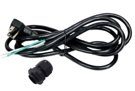
IMPORTANT: If you are using the plug-in method, the wiring is exactly the same but you will require an outlet. The plug referred to as a Pigtail (three wires including neutral, hot, and ground) can be purchased at most hardware outlets or a Hunter Authorized Dealer (P/N: PIGTAIL).
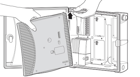
| REMOVE FACEPACK |
- Turn AC power off at the source, and verify that it is off.
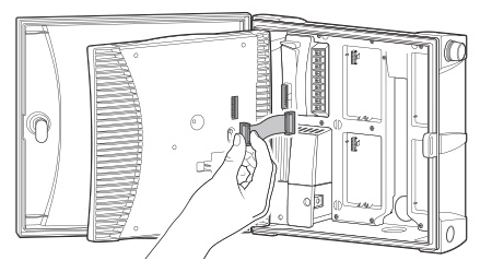
- Disconnect the facepack ribbon cable
- Remove the facepack.
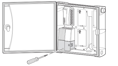
- Remove the cover from the junction box.
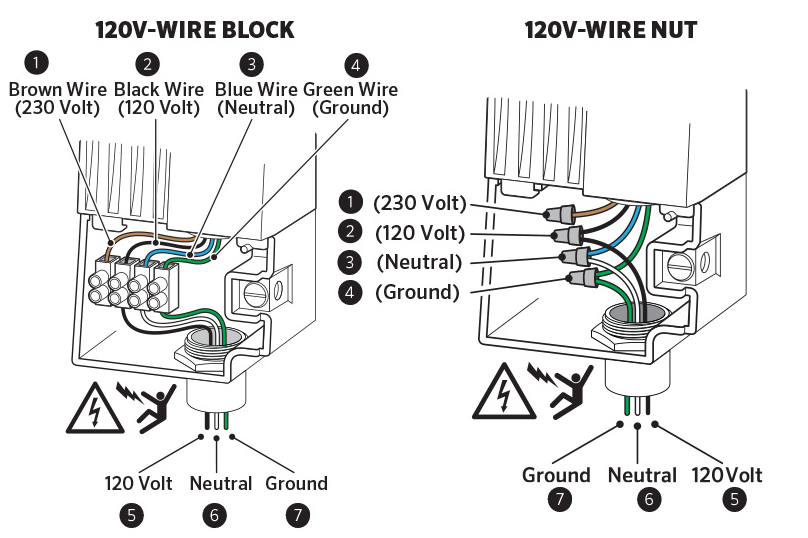
| WIRING |
-
Strip about 0.5” (13 mm) of insulation from the end of each AC power wire.
-
Route the wires through the conduit opening inside the junction box.
-
Connect the incoming black power wire (HOT) with the black wire lead from the transformer.
-
Connect the incoming white wire (NEUTRAL) with the blue lead from the transformer.
-
Connect the incoming green wire (GROUND) with the green and yellow wire from the transformer.
-
Cap the unused brown wire coming from the transformer. Replace the cover of the junction box and screw it into place.
- Replace cover, turn on the power, and test.
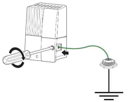
| EARTH GROUND CONNECTION (LIGHTNING PROTECTION) |
- Insert the copper wire from earth ground hardware, and tighten the screw in front.
- Minimum 10 AWG/5mm2 wire to earth ground hardware.
- Add copper-clad steel ground rods and/or plates sufficient to achieve 10Ω or less resistance at a minimum 8’/2.5 m away from the controller.
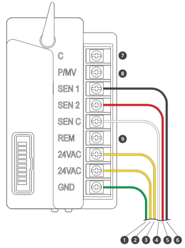
HCC - Power Module Wiring Diagram
| Power Module Terminals | |
| 1. Green | Ground |
| 2. Yellow | 24 VAC Transformer |
| 3. Yellow | 24 VAC Transformer |
| 4. White | Sensor Common |
| 5. Red | Rain Sensor |
| 6. Black | Flow Meter |
| 7. C | Common |
| 8. P/MV | Pump or Master Valve |
| 9. REM | Remote Control Input |
| 10. White | Sensor Common |
| 8. Red | Rain Sensor |
| 9. Black | Flow Meter |
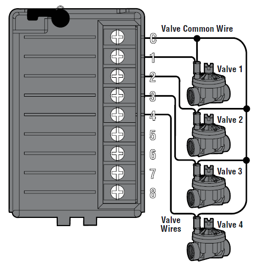
HCC - Valve Wiring
- Route valve wires between control valve location and controller.
- At valves, attach a common wire to either solenoid wire of all valves. The most commonly used color for the common wire is white. Attach a separate control wire to the remaining wire of each valve. All wire splice connections should be done using waterproof connectors.
- Open hinged faceplate on the controller to access the terminal strip area.
- Route valve wires through the conduit and attach conduit to the controller at the large conduit opening on the right side of the bottom of the cabinet. The conduit opening has a triple knockout to accommodate 1", 1¼", or 1½" (25, 32, or 40 mm) conduit. Each section can be easily removed using a knife.
- Strip ½" (13 mm) of insulation from ends of all wires. Secure valve common wire to C (Common) terminal on any of the valve modules or power module. Then attach all individual valve control wires to appropriate station terminals.
| HCC CONTROLLER |
|
HCC - Installing ICM Station Modules
The base model of HCC is supplied with an ICM-800 station output module. The capacity of the controller is increased when new station modules are installed and recognized.
Standard ICM station modules are available in 4, 8, and 22 station sizes (ICM-400, ICM-800, ICM-2200). These may be added at any time after initial installation.
IMPORTANT: The ICM-2200 (22 Station module) must always be installed in the last two module slots to make it compatible. All slots before the ICM-2200 must be filled with ICM-800 station modules.
| Model | Max Station Count | Total ICM 800 Modules | Total ICM 2200 Modules |
| HCC-800-PL | 38 |
Qty:2 - ICM-800 |
Qty:1 - ICM-2200 |
| HCC-800-M | 54 |
Qty:4 - ICM-800 |
Qty:1 - ICM-2200 |
| HCC-800-SS | 54 |
Qty:4 - ICM-800 |
Qty:1 - ICM-2200 |
| HCC-800-PP | 54 |
Qty:4 - ICM-800 |
Qty:1 - ICM-2200 |
STEP 1: Open the controller inner panel, and choose the next available open slot in the controller. Slots are numbered down the first column and up the second.
STEP 2: Flip the blue locking lever into the vertical unlocked position.
STEP 3: Tip the two tabs on one end of the module into the mating holes in one end of the slot, and tip the module firmly into place.
STEP 4: Flip the locking lever into the horizontal locked position.
STEP 5: Press the Reset button on the back of the controller control panel. This is required for the controller to recognize the new module.
STEP 6: Connect field and common wiring as needed and test.
HCC - Wire Distance to Valves
Below is a chart indicating the maximum wire run between the controller and the Hunter AC solenoid valves.
|
Valve Wire Sizing (Feet) |
|||||||
| Ground | Control Wire | ||||||
| 18 | 16 | 14 | 12 | 10 | 8 | 6 | |
| 18 | 850 | 1040 | 1210 | 1350 | 1460 | 1540 | 1590 |
| 16 | 1040 | 1340 | 1650 | 1920 | 2150 | 2330 | 2440 |
| 14 | 1210 | 1650 | 2150 | 2630 | 3080 | 3450 | 3700 |
| 12 | 1350 | 1920 | 2630 | 3390 | 4170 | 4880 | 5400 |
| 10 | 1460 | 2150 | 3080 | 4170 | 5400 | 6670 | 7650 |
| 8 | 1540 | 2330 | 3450 | 4880 | 6670 | 8700 | 10530 |
| 6 | 1590 | 2440 | 3700 | 54000 | 7690 | 10530 | 13330 |
Notes:
Maximum one-way distance in feet between controller and valve heavy-duty solenoid: 24 VAC, 350 mA inrush current, 190 mA holding current, 60 Hz; 370 mA inrush current, 210 mA holding current, 50 Hz
|
Valve Wire Sizing (Metric) |
||||||
| Ground | Control Wire | |||||
| 0.5 | 1 | 1.5 | 2.5 | 4 | 6 | |
| 0.5 | 140 | 190 | 210 | 235 | 250 | 260 |
| 1.0 | 190 | 290 | 335 | 415 | 465 | 495 |
| 1.5 | 208 | 335 | 397 | 515 | 595 | 647 |
| 2.5 | 235 | 415 | 515 | 730 | 900 | 1030 |
| 4.0 | 250 | 465 | 595 | 900 | 1175 | 1405 |
| 6.0 | 260 | 495 | 647 | 1030 | 1405 | 1745 |
Notes:
Maximum one-way distance in meters between controller and valve Heavy-duty solenoid: 24 VAC,
350 mA inrush current, 190 mA holding current, 60 Hz; 370 mA inrush current, 210 mA holding current, 50 Hz
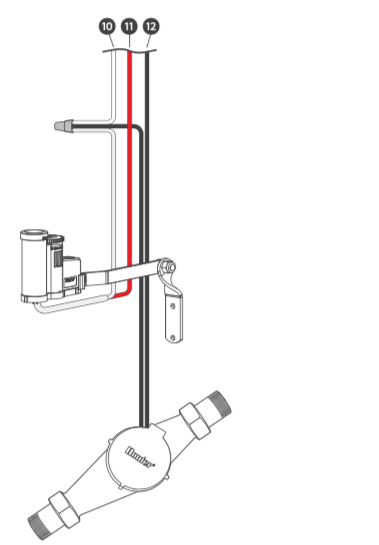
HCC - Connecting Sensors or Flow Meters (Optional)
The HCC Controller supports most open/closed contact types of sensors. Compatible Hunter flow meters and sensors include the HC FLOW METER, MINI-CLIK®, RAIN-CLIK™, FREEZE-CLIK®, WIND-CLIK™, and SOIL-CLIK™.
- Route the WIRES from the rain sensor up through the same conduit
opening used for valve wiring. - Connect the first wire to the terminal labeled SEN-1 or SEN-2.
- Install the second white wire to the other SEN (COM) terminal. See chart below.
| Rain Sensor | Flow Meter |
HCC - Installing Wi-Fi Antenna Extension Kit
To improve Wi-Fi visibility to the router, we recommend using the Wi-Fi extension kit (model: WIFI-EXT-KIT). This is not a signal booster, but an option to get the antenna closer to the router. Going around corners, through obstructions, or just reducing the distance are appropriate applications for this product.
The extension kit comes with two separate cables and mounting hardware to install in ¾" conduit. The thicker cable provides a 9' extension, while the thinner cable is 3.5' in length.
IMPORTANT: The 3.5' length cable is not used for the HCC Controller model. Use only one cable extension, as combining the two will incur a signal loss.
| WIFI-EXT-KIT: Parts Included | Controller Models |
| Cable 9' | Used for HCC and ACC2 model controllers. |
| SMA Adapter (red cap) | Used only for HCC model controllers. |
| Conduit Mounting Hardware | Used for HCC and ACC2 model controllers. |
Please visit an authorized Hunter distributor near you using our interactive Distributor Lookup
| Steps | Illustrations |
| Step 1: Open the FRONT PANEL to access the antenna compartment. | 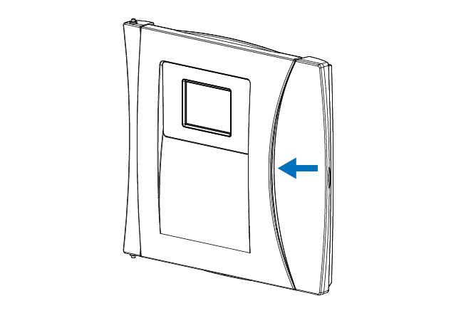 |
| Step 2: Remove the three Phillips SCREWS on the left-hand side of the back of the panel. | 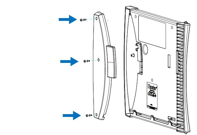 |
| Step 3: Unthread the existing antenna. Thread on the included SMA Adapter (red cap) until hand tightened. Next, thread on the extension cable (9') until hand tightened. Attach the original antenna to the other end of the cable. | 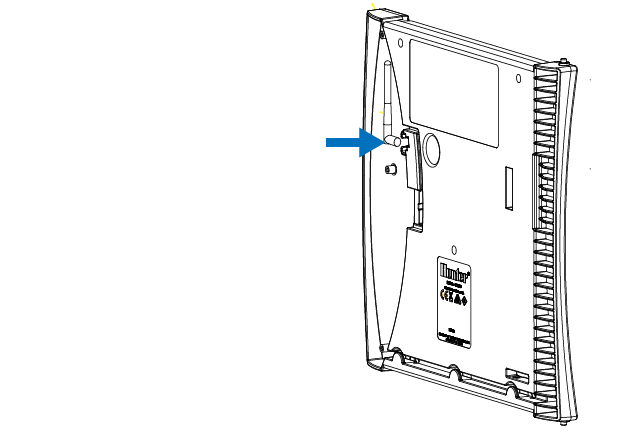 |
| Step 4: Route antenna cable through the channel at the bottom of the facepack. Remember to re-install the plastic cover over the compartment. Note: Drilling into the cabinet is not recommended. Please only use existing conduit knockouts. | 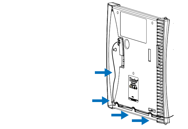 |
| Step 5: Route the 9' antenna cable from enclosure through ¾" (20 mm) plastic electrical conduit. Use standard fittings to position the antenna where required. Do not exceed supplied cable length. | 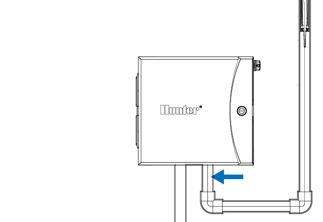 |
| Step 6: Route cable and antenna through standard ¾" (20 mm) threaded adapter with male threaded end up. | 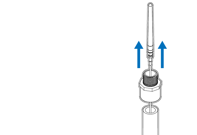 |
| Step 7: Insert the antenna into the open side of the lower tube (fit the cable through the slot). Adjust holder length by sliding the upper body into the lower body. | 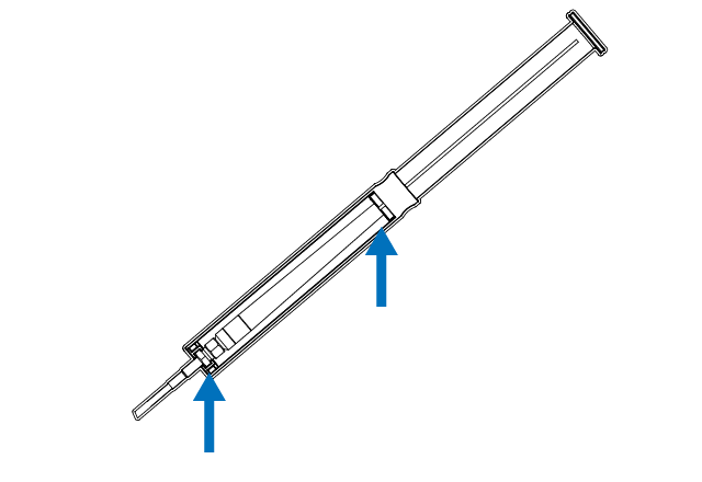 |
| Step 8: Drop the antenna holder into threaded conduit fitting, and allow the holder rim to rest on top of the fitting. | 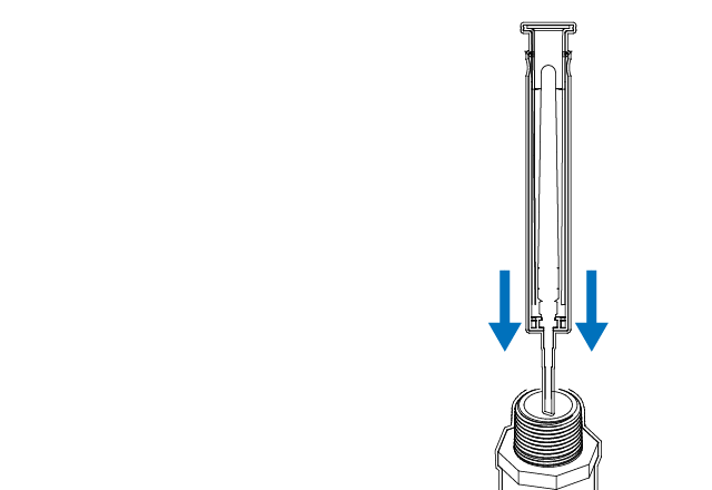 |
| Step 9: Add threaded cap (recommended) or glue cap to prevent water entry and complete installation. | 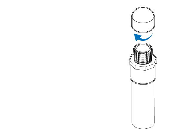 |
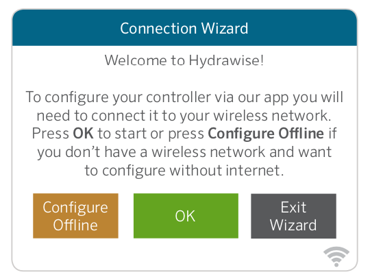
HCC - Configure Controller Offline
From the Connection Wizard screen, touch CONFIGURE OFFLINE. Tap OK to move on to the next step.
Enter in today’s date if it hasn’t already been set or if it is incorrect. Enter today’s time if it hasn’t already been set or if it is incorrect. From this screen, touch OK.
Next enable a MASTER VALVE, if you don't have a master valve then choose DISABLE MASTER VALVE. Then touch OK.
You can now enter the run length you want for your default zone run time. Then touch OK.
Next, set how often each zone will run. As advised on the previous screen, you can set individual frequencies for each zone. Touch OK to proceed. From ZONES screen, you can manually configure each zone according to your desired schedule. Touch the ADD button to add a program start time and follow the steps below. You can toggle between zones by touching NEXT or PREVIOUS buttons or you can leave the start time to APPLY TO ALL ZONES.