HPC - Upgrading Pro-C
The PRO-C model controller must be the NEWER PC- 400 version (blue buttons and solar sync dial position) with a date code of MARCH 2014 or newer. This date code is written on the white sticker inside the wiring compartment. Ensure you have a strong Wi-Fi signal. Wi-Fi connectivity can be tested on the HPC panel itself (signal strength is shown when you select a wireless network). If you have any issues connecting the controller to the router, please verify all Wi-Fi specifications here.
If you have the older model PC-300, the replacement controller is the HPC-400. If the station modules in your older unit are black, they will work in the HPC-400 model controller.
| PC-400 (Blue Buttons) Compatible | PC-300 (Green Buttons) Not Compatible |
NOTE: The compatible ribbon design in this panel should have two rows of pins. The single row of pins would also indicate a panel that is not compatible.
Remove Pro-C Face Panel
- Remove ribbon cable with power off.
- Press down on the white hinge release button.
- Remove face panel.
Install HPC-FP Face Panel
- Press blue hinges together and attach a new HPC panel.
- Reconnect ribbon cable
- Close and turn the power on
| STEPS |
For information on the complete setup in the application, please visit our USING THE APP section.
HPC - Using Hunter Remotes
The HPC face panel quickly and easily upgrades Pro-C® controllers (PC400 models manufactured since March 2014) to next-generation smart controllers via the Hydrawise platform. In addition, it lets contractors continue using their Roam and Roam XL remotes for quick on-site management. HCC is also compatible with Hunter’s ROAM and ROAM XL remotes, allowing for fast and reliable manual operation in the field from long-range distances without the need for a smartphone. There is no need to remove the smart port adapter from the controllers when doing a facepack upgrade.
Compatible models include all Hunter remotes: SRR, ICR, ROAM, and the ROAM-XL.
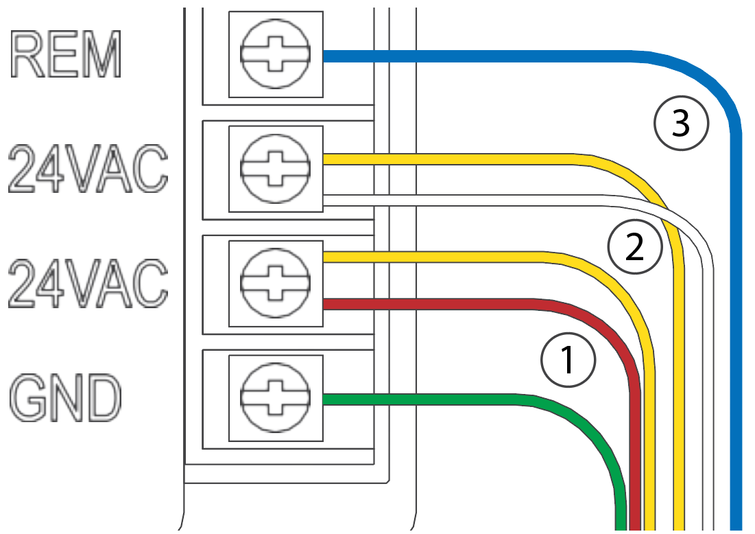
If the Smartport is not installed on the controller, see illustrations below for wiring instructions.
Note: Any extension of the wiring on the SmartPort may result in an error message in
the controller display and possible malfunction of the remote unit due to radio interference. In
some situations, lengthening of the harness may work fine, in others it may not work at all (it is
site specific). In either case, extending the wiring harness should be done using shielded cable to
minimize the possible effects of electrical noise. For easiest installation, order the Hunter SmartPort shielded cable wiring harness. (P/N ROAM-SCWH) with a full 25' (7.6 meters) of
shielded cable.
Wiring
- Bottom 24 VAC terminal - Red wire
- Second 24 VAC terminal - White wire
- Remote terminal - Blue wire
| Smart Port Wiring |
 |
Operation
The ROAM System will allow you to remotely turn on and off any station on your Hunter controller with the press of a button. Once on, the station will run for the run time you have designated in the remote. To remotely activate a station, follow the steps below:
- Plug the receiver into a SmartPort® that is connected to a powered controller. The receiver will beep 4 times followed by a 10-second pause and a single beep.
- If your transmitter is not on (no display), wake it up by pressing and holding the MODE button for 5 seconds. The Transmitter will display the active station.
- Use the up and down buttons to display the station you would like to start.
- Press the "Green Play Button" to start the station. The Transmitter will display the Transmit icon . If you are near the receiver, you will hear it beep 2 times. This indicates that the Receiver has received the command.
- Press the "Red Stop Button" to turn off any station that is on. The display will show the Transmit icon and receiver will beep again twice. The ROAM System is designed to turn on
one station at a time (unless you activate a program). Therefore, turning a station on
while another station is operating will cause the operating station to turn off.
NOTE: The ROAM remote can activate any station on the controller whether the controller dial is in the “SYSTEM OFF”, “RUN” or “RUN/BYPASS SENSOR” modes. If a sensor device has been wired to the controller, the ROAM remote will NOT override the sensor for manual operation. For more programming information, please see attached manuals for both the ROAM and ROAM XL remotes.
Lightning Transformers with Controllers
Hydrawise controllers are capable of operating lighting transformers equipped with the PXSYNC interface box. Commonly used transformers with the PXSYNC are the PX or EX models. We also offer a DX Transformer that can be controlled from an irrigation controller via the 24-volt EXTERNAL connection built inside the controller.
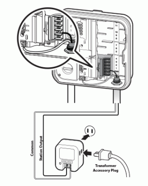
Connect wires from the first PXSYNC or external ports inside the DX box to a station output number (and the Common) on the Hydrawise controller. See the wiring illustration example below:
NOTE: If the controller is using a Pump or Master Valve, please reference the chart below for important information.

| Controller | P/MV Terminal | Output |
| HC |
If a pump or master valve is in use, the lighting transformer should not be used in conjunction with the irrigation controller.
|
Single station output will operate one at a time. Irrigation must not be programmed for the duration of the lighting schedule.
|
| WAND for X2 |
If using PUMP or master valve, this station output must be set to OFF in the programming.
|
Single station output will operate at a time. Irrigation must not be programmed for the duration of the lighting schedule.
|
| PRO-HC | If a pump or master valve is in use, the lighting transformer should not be used in conjunction with the irrigation controller. | Single station output will operate at a time. Irrigation must not be programmed for the duration of the lighting schedule. |
| HPC | If using PUMP or master valve, this station output must be set to OFF in the programming. | Single station output will operate at a time. Irrigation must not be programmed for the duration of the lighting schedule. |
| HCC | If using PUMP or master valve, this station output must be set to OFF in the programming. | Two station outputs will operate at a time. Any two programs will run simultaneously (lighting program and irrigation program). |
HPC- WRCLIK and HC Flow Meter
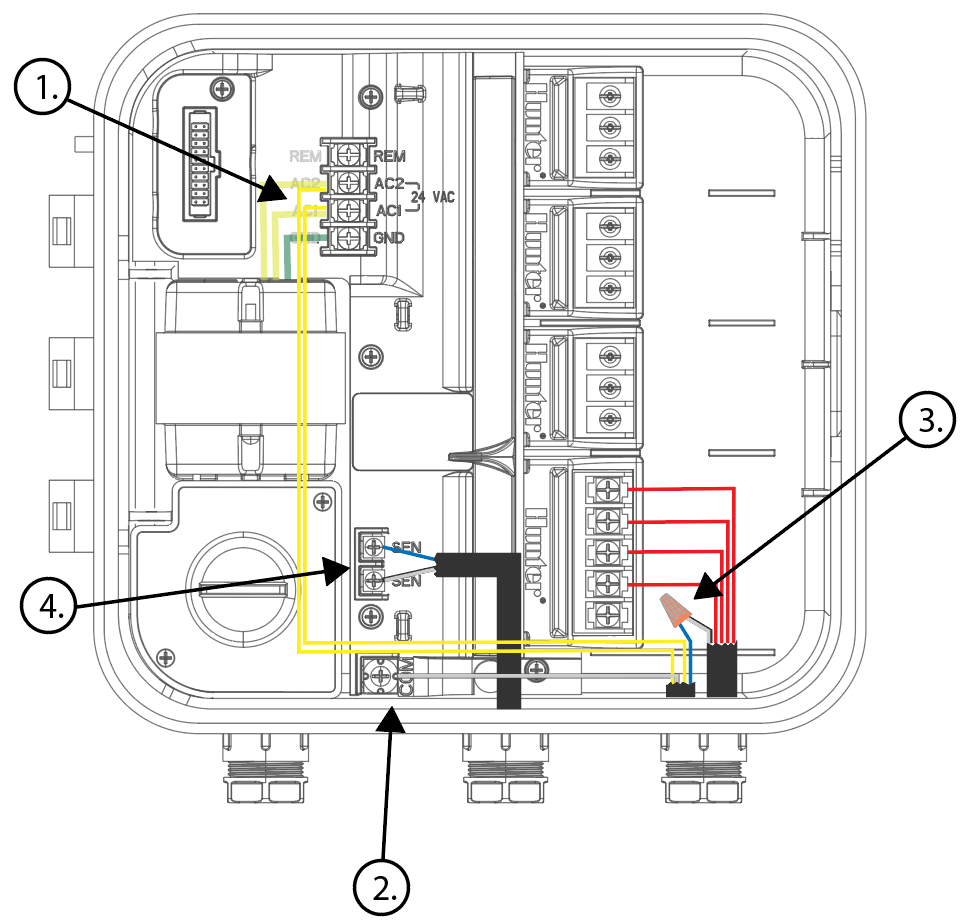
In the event you will need to install a flow meter and a rain sensor on the HPC controller, please use the following instructions. The HPC controller utilizes a single SEN output so these steps are necessary to make this work. For correct field wiring of the flow meter, please reference the article here.
NOTE: The software will only recognize the flow meter for this type of installation. The Wireless Rain Clik will still shut down system after a rain event, but this will not reflect anywhere in the software. The reports will not show ANY data for the rain events.
IMPORTANT: You will see alerts for underflow from the flow meter since the system will continue to run even with the common circuit interrupted by the rain event. These alerts will have to be ignored for this type of application. For more details on alerts, please view this article here.
Please reference chart and illustration below for controller wiring details.
| Illustration | Terminals | Wires |
| Figure 1. | AC 1/ AC 2 | WRCLIK Yellow |
| Figure 2. | COMMON | WRCLIK White |
| Figure 3. | Valve Common | WRCLIK Blue |
| Figure 4. | Flow meter - Blue/White | METER Blue/White |
| Right Click to View Larger image |
 |