HPC - Install Guide
HPC - Mounting the Controller
All necessary hardware is included for most installations.
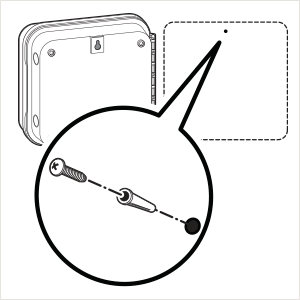
- Use the hole at the top of the controller as a reference and secure a 1" (25 mm) screw into the wall. Note: Install screw anchors if attaching to drywall or masonry wall.
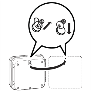
- Align controller with the screw and slide the keyhole on top of the controller over the screw.
- Secure controller in place by installing screws in the holes.
NOTE
The Indoor HPCis not weather or water resistant, and must be installed indoors or in a protected area. This device is not intended for use by young children. Never let children play with this device.
The Outdoor model is water and weather resistant. Connecting the outdoor HPC to the primary power should be done by a licensed electrician following all local codes. Improper installation could result in shock or fire hazard. This device is not intended for use by young children. Never let children play with this device.
HPC - Connecting AC Power
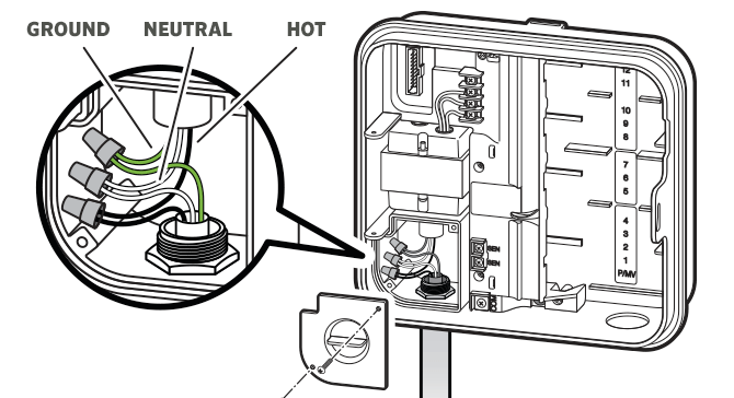
The outdoor model HPC comes with a pre-installed plug to allow the controller to plug in to an outlet easily. In the event you need to hard wire (wire directly to 120 VAC), the attached plastic grommet threads off easily and you can make the connection following the steps below.
- Route AC power cable and conduit through the ½" (13 mm) conduit opening on the left side of the bottom of the cabinet.
- Using the included wire nuts, connect the wires to the transformer wires located inside the junction box. International units are supplied with a built in terminal strip. Always use a UL listed conduit ½" (13 mm) male adapter when installing the AC wiring.
- Insert the adapter into the ½" (13 mm) hole at the bottom of the controller. Attach the nut to the adapter inside the enclosure.
NOTE: To be performed by a licensed electrician only.
Always use UL listed ½" (13 mm) conduit with male adapter when installing AC wiring. HPC controllers are intended to be supplied AC power with a 15A rated overcurrent protected device.
HPC - Installing Station Modules
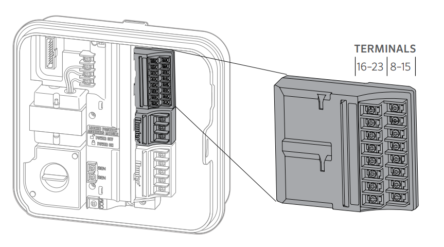
The Hydrawise enabled HPC Controller is supplied with a base 4-station module. Additional modules may be added separately in increments of 3 stations (PCM-300), 9 stations (PCM-900), or 16 stations (PCM-1600). In total, the system may be expanded up to 23 conventional stations. Additional modules are sold separately.
IMPORTANT: To expand your HPC Controller to 16 or 23 stations with a PCM-900 or PCM-1600 Module, you must install one PCM-300 Module in the first expansion slot (stations 5–7). Next, install the PCM-900 or PCM-1600 Module in the upper two expansion slots. These modules will not fit in any other station output slot. To use the PCM-1600 Module with an HPC Controller, the controller firmware must be version 4.31 or greater, and module firmware version 1.14 or greater. Check the version at the controller: Status > Controller (Connection) Status.
| Installing PCM-300/PCM-900 Modules |

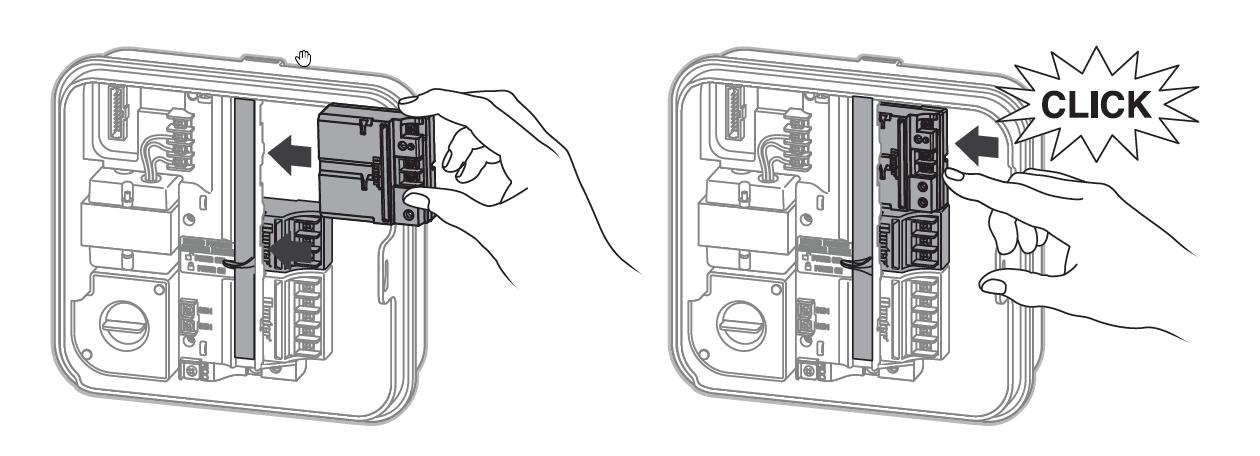
The HPC Controller is designed with a simple-to-use POWER LOCK feature that assures that the modules are energized and firmly secured into the controller. The POWER LOCK can unlock or lock all modules at one time by simply pushing the tab.
- Slide the POWER LOCK into the POWER OFF (unlocked) position. Insert the modules into the appropriate sequential position in the controller cabinet. Note: When in the POWER OFF (unlocked) position, the controller display will be blank.
- Once each module is in place, slide the POWER LOCK into the POWER ON (locked) position to energize and secure the modules into the controller.
- The controller will automatically recognize the correct number of stations. It is not necessary to press the reset button or cycle power to the controller.
| Installing the PCM-1600 Module |
- Slide the POWER LOCK into the POWER OFF (unlocked) position. Insert a PCM-300 Module into the middle output slot if not installed already.
- Insert the PCM-1600 Module into the top output slot.
- Once all modules are in place, slide the POWER LOCK into the POWER ON (locked) position to energize and secure the modules into the controller.
- The controller will automatically recognize the correct number of stations. In some cases, it may be necessary to cycle power to the controller.
HPC - Installing Decoder Module
The HPC controller is supplied with a base 4-station module. This controller is also compatible with the EZ Decoder System (EZDS) for hybrid conventional and two-wire operations. Add a Decoder Module (PC-DM) to enable control for up to 32 total stations. This system uses the same EZ-1 decoders used with ICC2 and HCC controllers.
EZ Decoder Connections and Programming
Installing the PC-DM Decoder Module
The PC-DM can only be installed in the last two station output slots (similar to PCM-900 and PCM-1600 installation). The PC-DM will not physically fit or operate in any other station output slot.
IMPORTANT: While adding this module increases the total station count to 32, the first 4 stations cannot be programmed as decoders and must be wired conventionally to the 4-station master module. This leaves stations 5–32 available for EZ decoder operation. This allows for hybrid conventional/decoder operation. If only EZ decoders are to be used, there are 28 total stations available, and the first station must be programmed as station 5.
As shown below, if stations 1–4 are conventionally wired, then stations 5–32 would be available for two-wire via PC-DM. Similarly, a 3-station PCM-300 expansion module could be added to the second station output slot, which would allow for stations 1–7 to be conventionally wired, and stations 8–32 available for two-wire.

Installing Additional Station Modules
- Slide the POWER LOCK into the POWER OFF (unlocked) position. Insert any additional station modules into the appropriate output slots.
- Once all of the modules are in place, slide the POWER LOCK into the POWER ON (locked) position to energize and secure the modules into the controller.
- The HPC will automatically recognize the correct number of stations. In some cases, it may be necessary to press the reset button on the back of the face pack or cycle power to the controller.
EZ-1 Decoder Connections and Programming
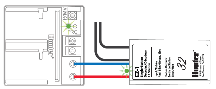
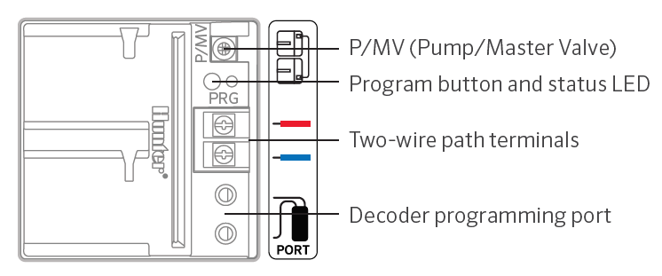
- Remove wire insulation, and insert red and blue wires from the decoder into the programming port (it doesn’t matter which wire goes into which hole).
- Manually start the station you want to assign to the decoder. This can be done using the controller face panel or remote control, if so equipped.
- When the station is running, push the “PRG” button on the PC-DM. The LED on the PC-DM and on the EZ-1 decoder will flash green once to indicate the decoder has been programmed.
- To assign a decoder as a P/MV, complete steps 1–3; however, don’t start any stations.
EZ-1 Decoder with P/MV
To activate a P/MV via decoder, connect a jumper wire from the P/MV on the PC-DM to the P/MV terminal on the 4-station master module (as shown in the icon next to the P/MV terminal). This wire can be a simple 18G station wire stripped 1/2" on each end that bridges these two terminals to allow operation. See the illustration below.
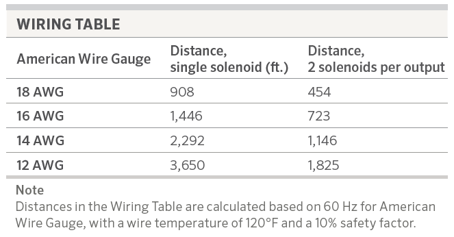
Wire Table
HPC - Connecting Station Wires
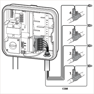
- Route valve wires between control valve location and controller.
- At valves, attach a common wire to either solenoid wire of all valves. This is most commonly a white colored wire. Attach a separate control wire to the remaining wire of each valve. All wire splice connections should be done using waterproof connectors.
- Route valve wires through the conduit and attach conduit to one of the openings on the bottom of the cabinet.
- Strip ½" (13 mm) of insulation from ends of all wires. Secure the valve common wire to “COM” (Common) terminal. Attach all individual valve control wires to the appropriate station terminals.
HPC - Connecting Sensors or Flow Meters (Optional)
HPC Controllers with date codes of JAN 2023 and newer include two sensor inputs. The SEN-SEN terminals from the original HPC Controllers have been split into SEN and SEN-2 to allow for two separate sensor installations (i.e., flow + rain sensor). Sensors now wire separately across the Common terminal (COM).
| Front Panel (Old vs New) | Terminals | Notes |
| HPC Front Panel (Pre-JAN 2023) | SEN/SEN | Currently, only compatible with a single flow/clik sensor. If the front panel (HPC-FP) is upgraded with a 2023 JAN or newer version, there is the option to use the two-sensor configuration. |
| HPC Front Panel (JAN 2023 or Newer) | SEN/SEN-2/COM | Compatible with two sensors. |
| Flow Meter Wiring | |
| Wire Color | Sensor Terminal Block |
| Blue | SEN or SEN 2 |
| White | COMMON |
| Clik Sensor Wiring | |
| Wire | Sensor Terminal Block |
| Normally Open (NO) or Normally Closed (NC) | SEN or SEN 2 |
| Secondary Wire | COMMON |