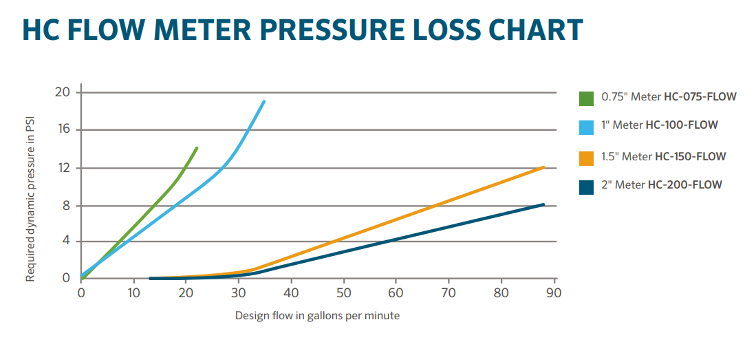
Flow Meter Pressure Loss Chart
How to Configure Your Flow Meter
Assigning the Meter
Please view the steps and screenshots to access this feature:
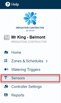
- Click on SENSORS from the home dashboard.
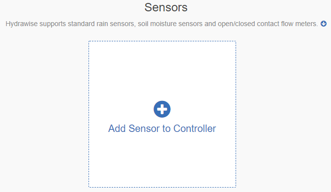
- Click on ADD SENSOR TO CONTROLLER.
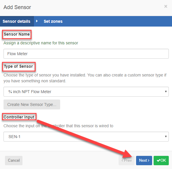
- Choose a NAME, SENSOR TYPE, and INPUT (flow-related only).
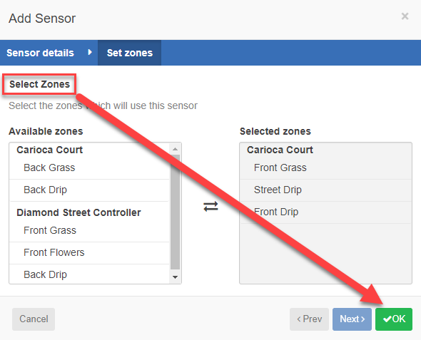
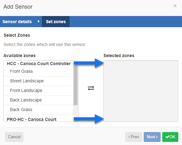
- Choose which ZONES should be linked to the sensor.
- Click OK when finished.
| Step 1 |
 |
| Step 2 |
 |
| Step 3 |
 |
| Step 4 |
 |
Flow Meter Installation Quick Start Guide
In this Quick Start Guide, you will learn how to install and configure your flow meter. For support of Hydrawise™ cloud software or help with your Hydrawise account, visit the support section here. For specification information, refer to the section here.
The flow meter consists of two parts: |
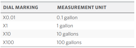
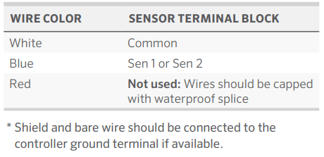
1. Flowmeter body: The flowmeter body contains an analog dial for manual readings as follows. Your flow meter will have 3 wires protruding from the body. The wires need to be connected to the sensor inputs on the controller for readings in the software application. In all models, only 2 wires (blue and white) are used.
2. Adapter: Each flow meter has an adapter to allow connection to your irrigation system.
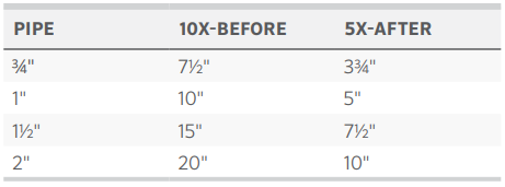
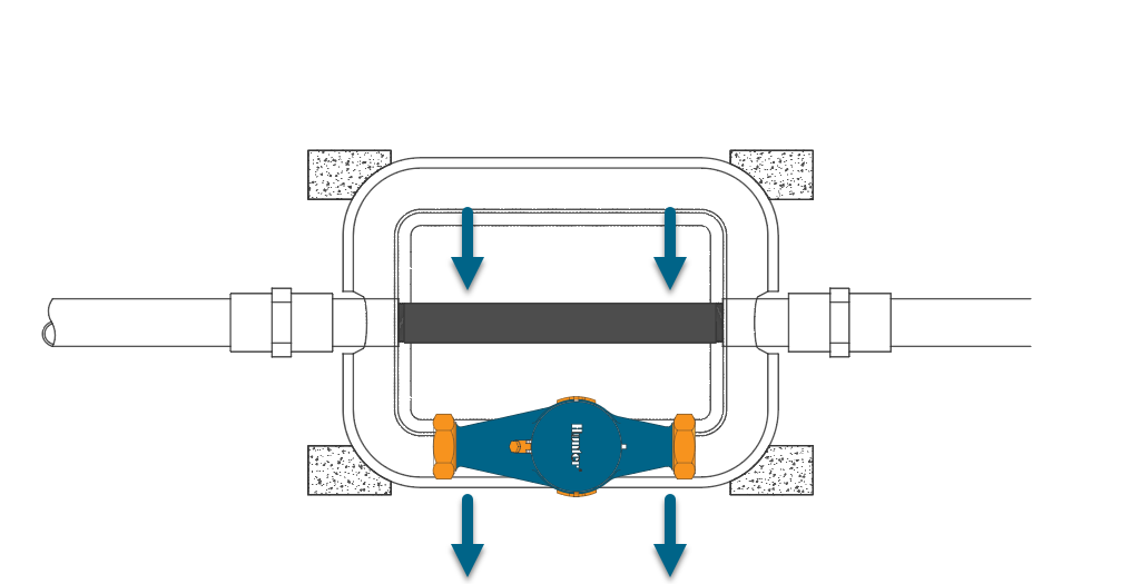
3. Flowmeter location: Flow meters are installed between the master valve and zone valves. To avoid false alerts, there should be no water taps or other uncontrolled water use on the downstream side of the flow meter. If all solenoids connected to the controller are not grouped together, it may be necessary to install more than one flow meter. For proper installation and optimal water flow, use the chart below when determining pipe length. The pipe bringing water into the flow meter needs to be 10 times longer than the width of the pipe. The pipe carrying water away from the meter needs to be 5 times the width of the pipe.
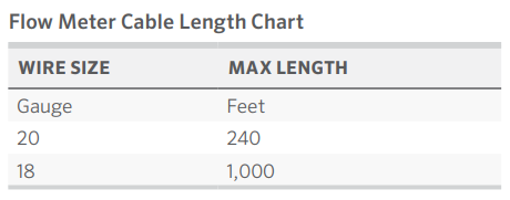
4. Cable (shielded direct-burial cable must be used): Two-wire cable is required. The cable gauge is determined by the total length of cable between the controller and the flow meter. The cable should consist of 2 dedicated wires and must not be in the same conduit or cable bunch as the solenoid wires. Do not share the common wire of the solenoids with the common of the sensors. If desired, the flex cable can be used to run inside the conduit. That flex cable measures ¼” BSP, which also fits ¼” NPT.
IMPORTANT: Shielded direct-burial cable is commonly available. Manufacturers include Paige Electric and Regency Wire.
The following instructions assume you have already installed your Hydrawise controller |
1. Flowmeter body: The flow meter has a marking on the body indicating the direction of water flow. Installation of the flow meter must be in the correct orientation with water flowing in the direction of the arrow on the flow meter body. All HC Flow Meters must be installed horizontally with the dial facing upward.
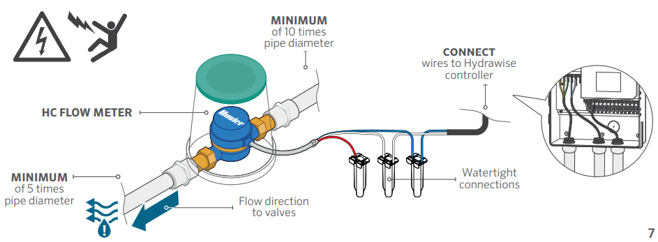
2. Connect flowmeter wire: Two-wire cable is required. The cable required to connect your flow meter must be dedicated to the flow meter and not shared with the common wire of the valves or other sensors. The cable gauge is determined by the total length of cable between the controller and the flow meter. The general rule is that 0.5 mm (20GA) wire is good for a run of up to 240'. Connect the wires to your Hydrawise controller.
IMPORTANT: All wire connections should be done using waterproof connectors, such as 3M 316IR or 3M DBY.
Use your Hydrawise account to complete your flow meter configuration. |
1. Log in to your account: Enter your login information.
2. Create a flow sensor: It is important that you select the correct flow meter when configuring your Hydrawise
app. Choosing the wrong model may cause the Hydrawise controller to create false alerts in the software.
3. Assign zones to the flow sensor: Refer to this support article for setup information.
Flow Meter Installation Tips
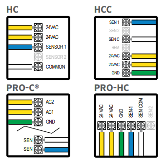
The flow meter wires need to be cabled back to the controller and connected to the Sensor inputs on the controller. Check out the illustrations below for wiring standard Hydrawise flow meters to each of the model controllers (Sizes include 3/4", 1", 1.5", and 2")
The tips below include all the necessary key points of the installation to avoid any false alerts or readings.
| Installation Steps | Description | |||||||||||||||
| Flow Meter Body | Flow meters are designed to be installed horizontally only, with the dial facing up. Not vertically. Analog dial for manual readings in U.S. are shown in US gallons (Int. customers the dial reads in Cubic Meters). Units can be changed in App to gallons or liters. | |||||||||||||||
| Adapter | Brass unions included to fit your irrigation system. | |||||||||||||||
| Entry Location |
Install between the master valve and zone valves. Meter should be installed 10 times pipe diameter before and 5 times after with straight pipe and no fittings. See example:
|
|||||||||||||||
| Cable used (shielded cable only) | 18 gauge - 1000 foot max Length. Shielded direct burial cable must be used. Cable should consist of two dedicated wires and must not be in the same conduit, cable bundle or trench as the solenoid wires. DO NOT share common wire. Shielded cable is commonly available, here are some manufacturers (Paige & Regency For additional information on avoiding electrical interference, see below: | |||||||||||||||
| Flow meter body | Arrow indicates direction of flow. | |||||||||||||||
|
Wire Connection |
Blue/White wire only, red not used. See sensor configuration for more info based on model controller. | |||||||||||||||
| Log in to your account | Enter your login information. | |||||||||||||||
| Create your flow sensor | App will show options for all HC meters. | |||||||||||||||
| Creating Alerts | See link here | |||||||||||||||
| Reading Meter | See link here | |||||||||||||||
| Testing Meter | See link here |
Avoid Electrical Interference
- Always use shielded cable, between the controller and the HC Flow Meter.
- At the controller end, using the shield (foil wrap) and the bare wire connect them to the controller GND terminal (not required for HC controllers).
- Do not connect the other end of the Shield or the bare wire to the Earth or a grounding stake
- Use Waterproof wire connectors at the flow meter, such as the 3M-DBOB.
- Shielded cable is commonly available, here are some manufacturers. Paige & Regency
HC Flow Meter Specifications
HC FLOW METER SPECIFICATIONS
| HC Flow Model | HC-075-FLOW (¾") | HC-100-FLOW (1") | HC-150-FLOW (1½") | HC-200-FLOW (2") |
| Inlet/outlet connection size | ¾" NPT body, male thread | 1" NPT body, male thread | 1½" NPT body, male thread | 2" NPT body, male thread |
| Meter internal diameter | 3/4" | 1" | 1.5" | 2" |
| Minimum flow (GPM) | 0.22 | 0.3 | 0.88 | 1.98 |
| Maximum recommended flow (GPM) | 15 | 30 | 66 | 105 |
| Maximum flow rate (GPM) | 21 | 34 | 88 | 132 |
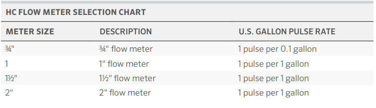
| Dial reading (US gal) | 1 pulse per 0.1 U.S. gal | 1 pulse per 1 U.S. gal | 1 pulse per 1 U.S. gal | 1 pulse per 1 U.S. gal |
| Maximum working pressure (PSI) | 230 | 230 | 230 | 230 |
| Included Wire Length | 29" total wire length with first 8" having flex conduit. | |||
| Flex Conduit Thread Spec |
Threading measures ¼” BSP, which would also fit ¼” NPT for all models. The exact thread size of the stainless steel fitting is 1/4-28. |
|||
|
|
||||
Reading Meter
The Hydrawise flow meters come in a US Gallon reading for domestic and metric reading called M³ (Meters Cubed 1000 Liters) for international. The conversion rate for metric meters is 3.78 Liters to 1 US Gallon if required.
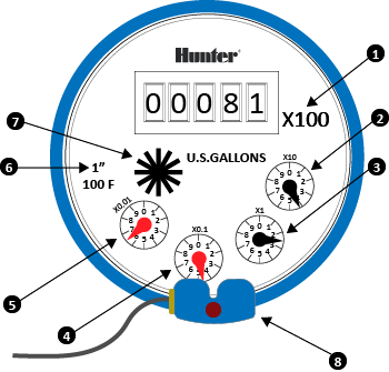
See an example of meter reading below in US gallons:
| Fig. 1 | X100 | 8100 Gallons |
| Fig. 2 | X10 | 814X.XX Gallons |
| Fig. 3 | X1 | 8142.XX Gallons |
| Fig. 4 | X0.1 | 8142.4X Gallons |
| Fig. 5 | X0.01 | 8142.46 Gallons Total |
| Fig. 6 | Size meter | 1" |
| Fig. 7 | Flow Indicator | Wheel spins when water is flowing. |
| Fig. 8 | Pulse Transmitter | 1-1/2” (40mm) & 2”(50mm ) flow meter models |
|
We have a flow that has gone through the meter of 8,142.46 gallons.
|
||
See an example of meter reading below in Litres:
| Fig. 1 | 8,000 Litres |
| Fig. 2 | 8,200 Litres |
| Fig. 3 | 8,220 Litres |
| Fig. 4 | 8,224 Litres |
| Fig. 5 | 8,224.7 Litres Total |
| Fig. 6 | The wheel spins when water is flowing. |
|
So we have a flow that has gone through the meter of 8,224.7 Litres. To calculate this into Gallons is easy 8,224.7 / 3.78 = 2175.84 gallons. |
|

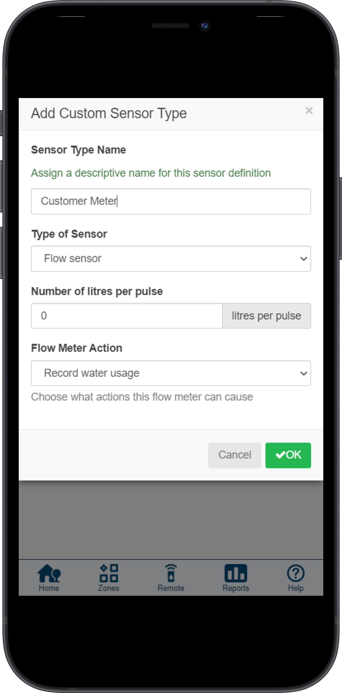
How to Configure a Custom Flow Meter
If you choose to use a flow meter from another manufacturer with a reed switch output, please make sure the configuration is set up under CUSTOM SENSOR TYPE.
- Log in to the Hydrawise app.
- Click the
 MENU icon on the upper left-hand side.
 -
Select the
 SENSORS option.
 - Select CUSTOM SENSOR TYPE.
- Select ADD CUSTOM SENSOR TYPE.
- A dialogue box will appear for you to enter your custom flow meter details. Make sure you enter the calibration details for your custom, pulse-based flow meter. Please refer to the manufacturer specifications to determine the calibration. Otherwise, you will not receive accurate readings to display on your flow data.
When using a third-party flow meter, please ensure it meets the specs above and is calibrated correctly. Otherwise, data will not reflect accurately in reports. Also, note that the wiring is not polarity sensitive. As long as you have one wire in a Sensor Port and a Sensor Common, the device will work correctly. For flow meters that use three wires and meet the specs above, configure the wiring until you find the two correct wires to use.
Using One Flow Meter for Two Controllers
For this installation, we suggest a few tips to make sure you do not receive any unnecessary alerts.
When using two controllers on the same flow meter, there are two alerts we do not recommend using.
- HIGH FLOW LEAK - High water usage with no zones running.
- SLOW LEAK - Water usage over last hour with no zones running.
These alerts are controller specific so when the controller with the flow meter is not in operation, it does know about the other controller operation.
Tips:
- The inter station delay should be set for 10-30 seconds. We do not recommend any higher.
- Change the gallons in the alert to be HIGHER (e.g. alert from 5 gallons to 20 gallons).
- Wire to only ONE of the two controllers.
- Configure the sensor to the controller that has the wire connection.
- Move AVAILABLE zones from both controllers into SELECTED ZONES.
For more information on configuring and wiring, visit support section here.
Following these parameters should allow the system to run normal when using one flow meter with multiple controllers.
Winterization - Bypassing a Flow Meter
Overview:
We recommend that a qualified licensed contractor perform this type of winterization method. The blowout method utilizes an air compressor with a cubic foot per minute (CFM) rating of 80-100 for any 2" or less mainline. The compressor is attached to the mainline via a quick coupler, hose bib, or other connections located beyond the backflow device. For additional winterization procedures, we highly recommend contacting the local dealer for the most common local practices.
IMPORTANT: Compressed air should not be blown through any backflow or flow meter device.
If you need to blow upstream from where the flow meter is located, we recommend bypassing the meter temporarily by using one of two options.
| Bypass HC Flow Meter Using Nipple |
See the size chart below for specific lengths to install an SCH 80 or galvanized nipple.
 |
| Model | Description | Male-Thread NPT | Nipple Length |
|
HC-075-FLOW |
¾" NPT body, male thread with 1" NPT male adapter |
1" NPT |
5" |
|
HC-100-FLOW |
1" NPT body, male thread with 1.5" NPT male adapter |
1 ¼"NPT |
5" |
|
HC-150-FLOW |
1½" NPT body, male thread with 2" NPT male adapter |
2"NPT |
11 3/4" |
|
HC-200-FLOW |
2" NPT body, male thread with 3" NPT male adapter |
2 1/2" BSP |
11 3/4" |
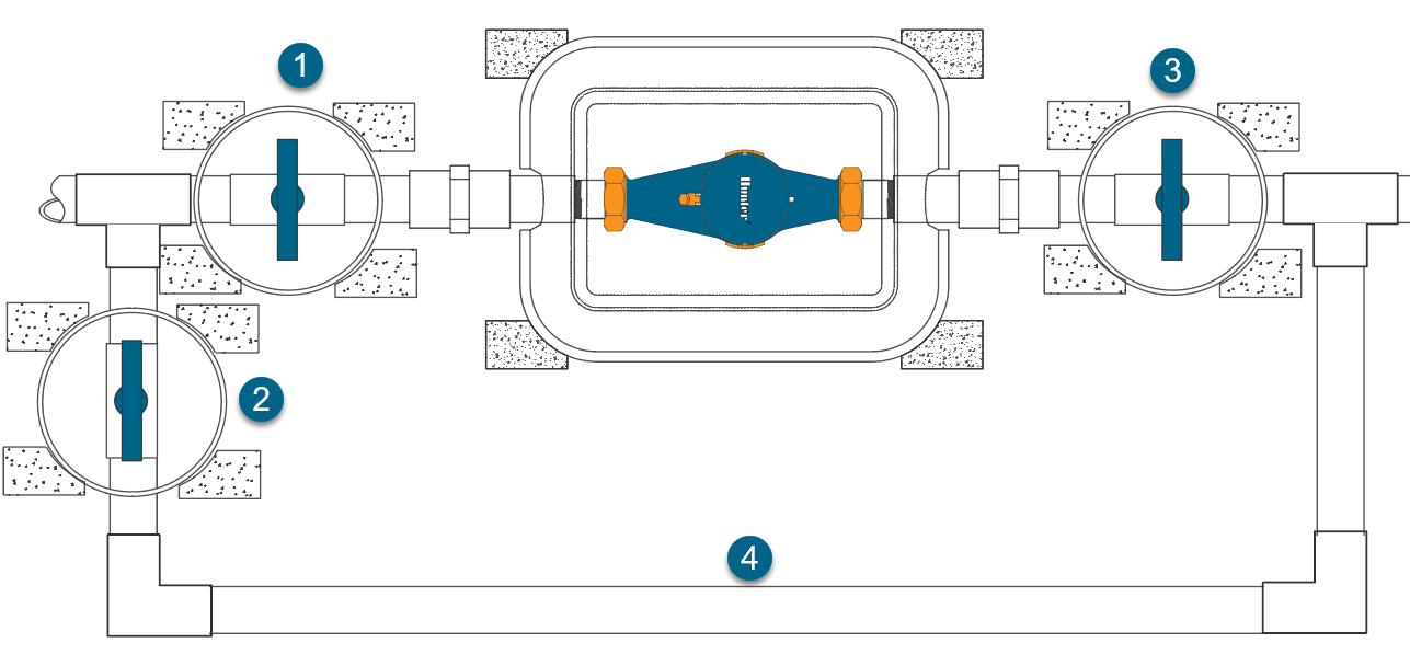
| Bypass HC Flow Meter Using Shutoff Valves |
A second option would be to install PVC tee-ball valves on each side of the meter. This is the recommended option during NEW installation. The meter will have to be removed manually after the blowout to make sure any residual water is not sitting inside through the winter months.
IMPORTANT: The pipe flowing water into the flow meter needs to be a MINIMUM of 10 times longer than the width of the pipe. The pipe flowing water away from the meter needs to be a MINIMUM of 5 times the width of the pipe.
- Ball Valve 1
- Ball Valve 2
- Ball Valve 3 (Not necessary for winterizing but helpful for maintenance on the meter)
- Bypass PVC pipe
 |
Find a Hunter Distributor closest to you using our interactive lookup - Get Hunter