Wire Distance (Controller to Valve)
The chart below indicates the maximum wire runs that can be used when installing Hunter AC solenoid valves with controllers. The example in the chart below demonstrates the most commonly used wire size for station control and ground wire ( e.g.,12 AWG = 3390 feet).
NOTE: Valve Wire Sizing (Maximum One-Way Distance in Feet Between Controller and Valve)
|
Ground Wire (size) |
Control Wire (FT) | |||||
| 18 AWG / 1.0 mm | 16 AWG / 1.2 mm | 14 AWG / 1.6 mm | 12 AWG / 2.0 mm | 10 AWG / 2.5 mm | 8 AWG / 3 mm | |
| 18 AWG / 1.0 mm | 850 | 1040 | 1210 | 1350 | 1460 | 1540 |
| 16 AWG / 1.2 mm | 1040 | 1340 | 1650 | 1920 | 2150 | 2330 |
| 14 AWG / 1.6 mm | 1210 | 1650 | 2150 | 2630 | 3080 | 3450 |
| 12 AWG / 2.0 mm | 1350 | 1920 | 2630 |
3390 |
4170 | 4880 |
| 10 AWG / 2.5 mm | 1460 | 2150 | 3080 | 4170 | 5400 | 6670 |
| 8 AWG / 3 mm | 1540 | 2330 | 3450 | 4880 | 6670 | 8700 |
Pump Start Relay Wiring and Software Setup
In this article, we will discuss the following topics:
- Summary
- Operation Chart
- Wiring (24 VAC)
- Wiring to Power Source
- Software Setup
- Pump Start Relay Operation per Zone
| Summary |
When a system requires the use of a booster pump or pulls water directly from a creek or pond, it’s imperative to include a relay to activate the pump each and every time. A pump start relay is a relay box that activates a pump every time a zone is activated from the controller. Zone valves are the individual valves that operate a group of sprinklers or drip emitters. Hydrawise controllers support 6- to 54-zone valves, depending on the model. Typically, one zone valve is turned on at a time and controls the irrigation in a specific area of your landscape. Whenever one of the irrigation zone valves is told to open by the controller, the controller also signals the pump start relay to turn the pump on.
| Operation Chart |
| Controller Model | Set Master Valve Operation |
| HC | ON or OFF by All Zones |
| PRO-HC | ON or OFF by All Zones |
| X2 w/WAND WiFi Module | ON or OFF by Zone or All Zones |
| HPC | ON or OFF by Zone or All Zones |
| HCC | ON or OFF by Zone or All Zones |
| Wiring (24 VAC) |
Use a minimum distance of 15' (4.5 m) between the controller and the relay to dampen electromagnetic noise. In addition to this recommendation, Hunter also recommends all controllers be mounted 15' (4.5 m) away from pumps and high-voltage devices.
- Detach the pump start relay cover plate by removing the four screws with a Phillips screwdriver.
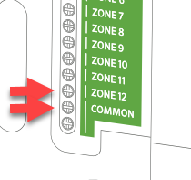
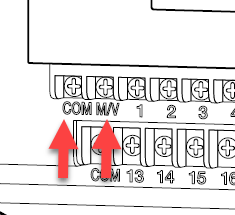
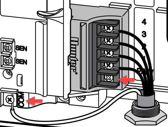
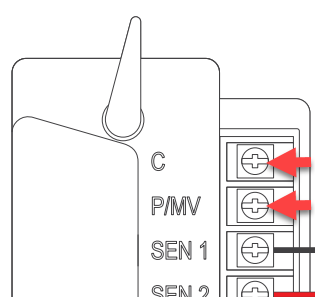
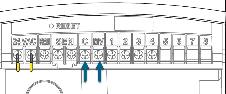
- Run a single wire from the "common" terminal on the controller to one of the yellow wires on the pump start relay.
- Run a single wire from the "P/MV" terminal on the controller to the other yellow wire on the pump start relay.
- Use wire nuts to make the connections and verify they are secure.
- Install pump start relay cover plate and four screws. Close and lock the cabinet door.
- Route wire through the conduit or one of the openings on the bottom of the cabinet.
- Strip ½" (13 mm) of insulation from the ends of all wires. Secure the valve common wire to the “COM” (Common) terminal. Attach the opposite control wire to the M/V terminal.
| Pump Start Relay Maximum Wire Lengths | ||||||
| MAXIMUM one-way wire length (do not go this far!) | ||||||
| Model | 18 AWG | 16 AWG | 14 AWG | 12 AWG | 10 AWG | 8 AWG |
| PSR-22 | 243 ft | 386 ft | 616 ft | 976 ft | 1,551 ft | 2,463 ft |
| PSR-52 | 134 ft | 214 ft | 341 ft | 540 ft | 859 ft | 1,365 ft |
| PSR-53 | 134 ft | 214 ft | 341 ft | 540 ft | 859 ft | 1,365 ft |
| Wiring Illustrations | |
| HC | PRO-HC |
 |
 |
| HPC | HCC |
 |
 |
| X2 w/WAND WiFi Module | |
 |
|
NOTE: With an HC Hydrawise controller, any one of your 6 or 12 zones can be configured to act as the pump start relay. We usually recommend wiring to the last zone that is not being used in the controller.
| Wiring to Power Source |
Connecting the pump start relay should only be done by a licensed electrician following local codes. Improper installation could result in shock or fire hazard.
- To prevent electric shock, turn the main circuit-breaker switch to “off” prior to making electrical connections.
- Assemble conduit piping and connect AC power from the power source to one side (LINE IN) of the relay.
- Assemble conduit piping and connect wiring from the pump motor to the other side of the relay (LOAD OUT).
- Check to make sure there are no exposed or loose connections.
| Software Setup |
This setup option is prompted when you first go through the initial setup wizard in the software.
The online instructions will refer to a MASTER VALVE but this same setting applies when using a PUMP START RELAY (PSR).
NOTE: With an HC Hydrawise controller, any one of your 6 or 12 zones can be configured to act as the pump start relay. We usually recommend wiring to the last zone that is not being used in the controller.
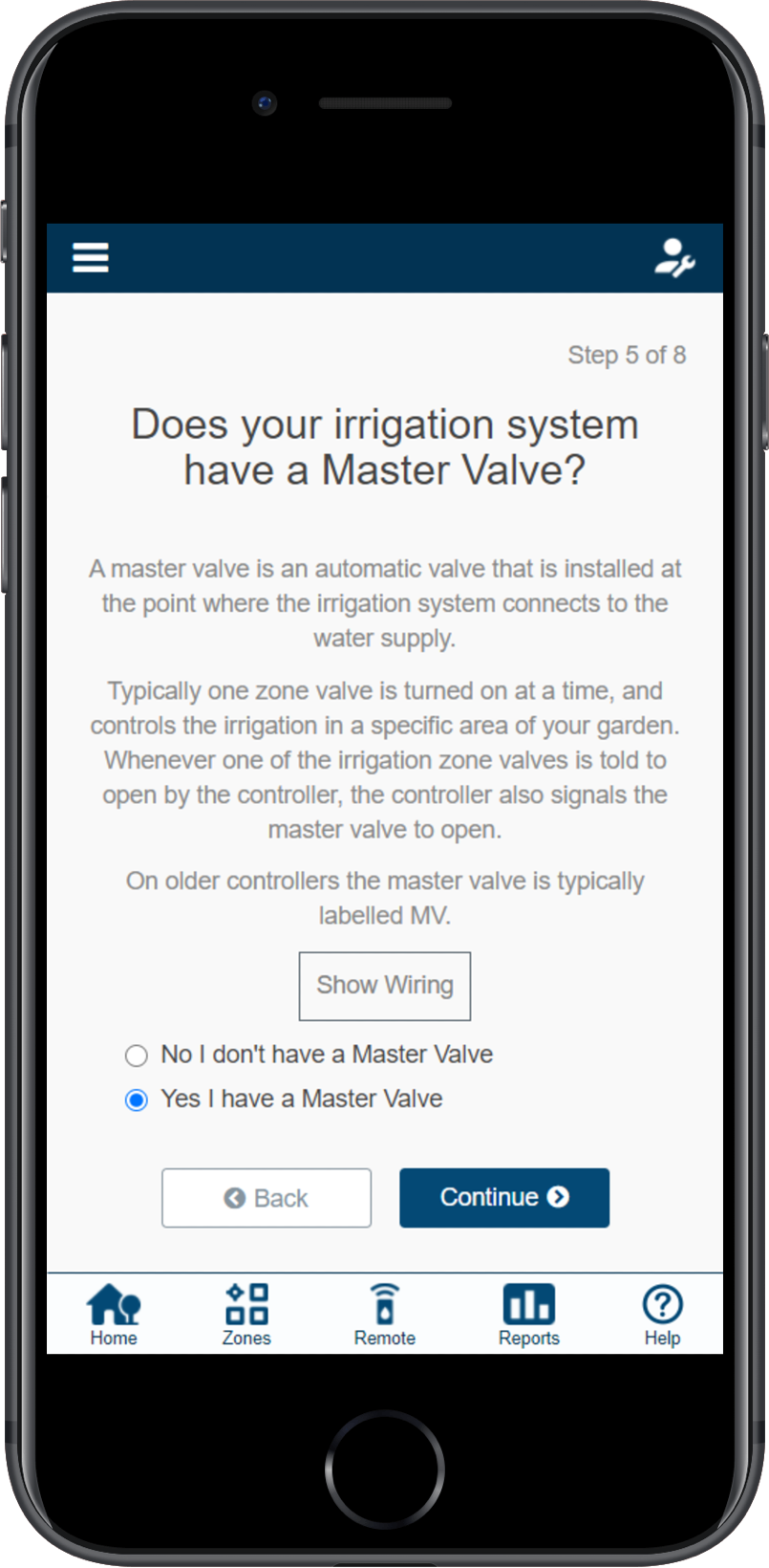
If you need to change this in the software after the setup wizard, refer to the instructions below.
- Log in to your Hydrawise account
- Click on ZONES AND SCHEDULES for the PC or ZONES if using the mobile app.
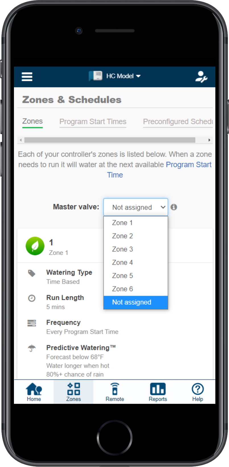
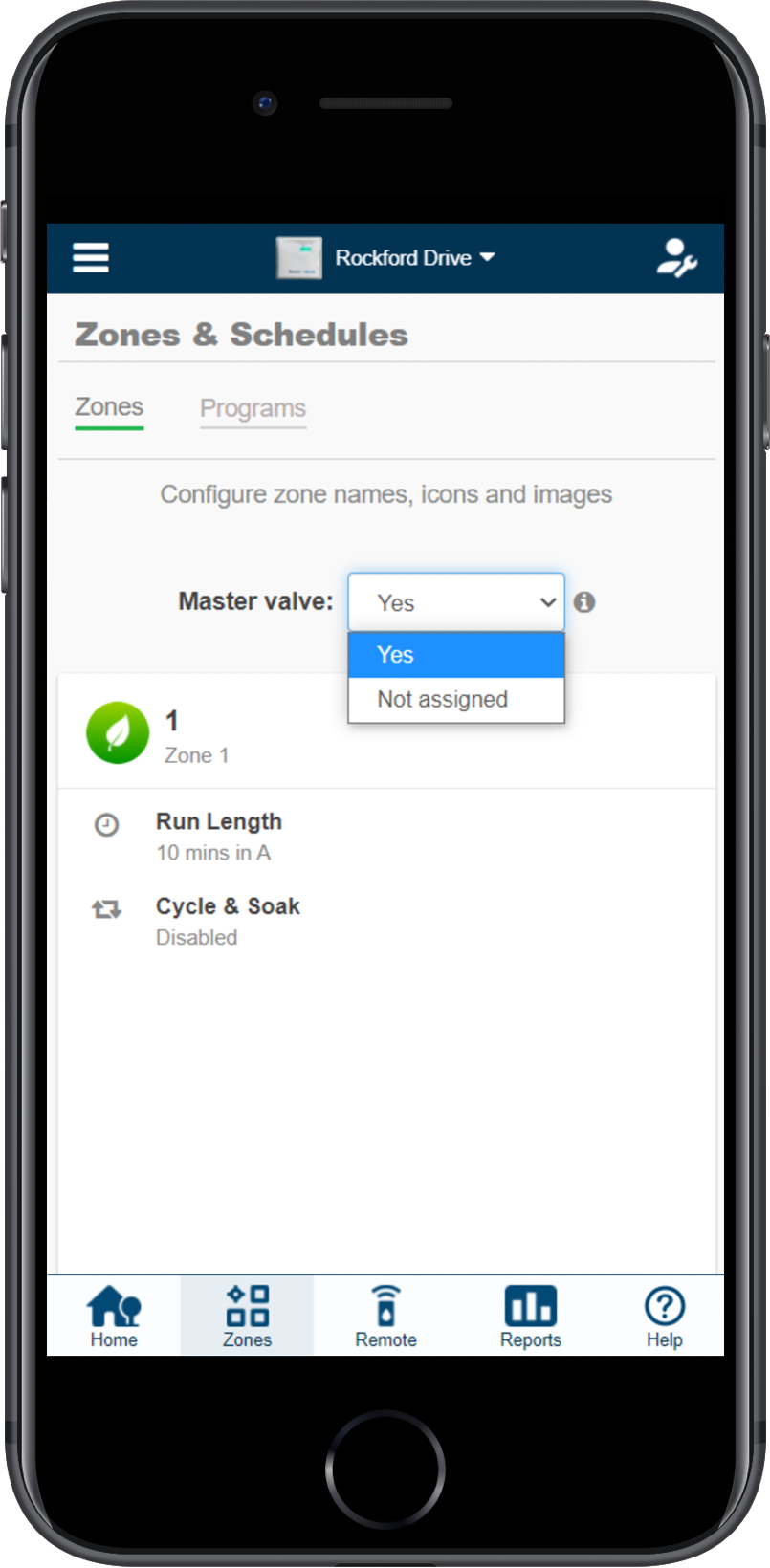
- Choose YES from the drop-down menu above the zones. If you have an HC controller, choose the zone number to which you have the master valve wired.
| HC Controller | X2 w/WAND, PRO-HC, HPC, and HCC Controllers |
 |
 |
| Pump Start Relay Operation per Station |
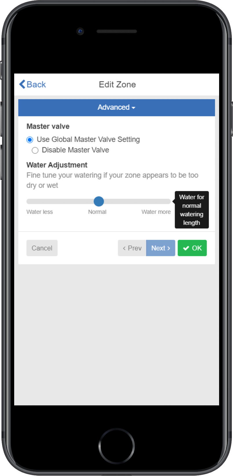
When selecting a PUMP START RELAY to be on/off for an individual zone, you can edit the zone in ZONES AND SCHEDULES under ADVANCED SETTINGS. This option is useful when one zone is using city water and another is using water from a different source. This option is for X2 w/WAND, HPC, and HCC controllers only.
Follow the steps below to change this setting:
- From the ZONES AND SCHEDULES page, click on the (
 ) icon on the zone you would like to edit.
 - Click on ADVANCED, which is located on the top blue search section.
- Select USE GLOBAL MASTER VALVE SETTING to keep this circuit on or select DISABLE MASTER VALVE to turn it off.
One Master Valve - Two Controllers
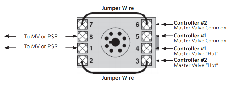
There are many times when two controllers are being supplied from a single POC (point of connection) or source of water. Hydrawise-ready controllers can be connected to a single master valve using a isolation relay (part number REL2). This device will allow for two controllers to share the same master valve with out any issues.
The few limitations include:
- Only one controller can operate at a time.
- A delay of at least five minutes between the operation of controller #1 and controller #2 is desirable.
- Electrical alerts will apply for each controller.
Steps for set up.
- Wire the relay according to the drawing below.
- Set up the master valve in the the app for both controllers using the normal instructions in the article here.
- Set up a new master valve using the app for controller #2 as per normal instructions.
REL 2 is NEVER connected to high voltage. It is for 24 VAC devices only.
Master Valve Wiring and Software Setup
In this article, we will discuss the following topics:
- Brief Summary
- Operation Chart
- Wiring
- Software Setup
- Master Valve (P/MV) Operation per zone
| Brief Summary |
A master valve is a normally closed valve installed at the supply point of the mainline that opens only when the automatic system is activated. Zone valves are the individual valves that operate a group of sprinklers or drip emitters. Hydrawise controllers support 6 - 54 zone valves, depending on the model. Typically one zone valve is turned on at a time and controls the irrigation in a specific area of your garden. Whenever one of the irrigation zone valves is told to open by the controller, the controller also signals the master valve to open. The purpose of the master valve is to shut off the water to the irrigation system when none of the zone valves are operating.
IMPORTANT: The default setting for the Pump Start Relay/Master Valve is NOT ASSIGNED (OFF) in the software settings.
| Operation Chart |
| Controller Model | Set Master Valve Operation |
| HC | ON or OFF by All Zones |
| PRO-HC | ON or OFF by All Zones |
| X2 w/WAND WiFi Module | ON or OFF by Zone or All Zones |
| HPC | ON or OFF by Zone or All Zones |
| HCC | ON or OFF by Zone or All Zones |
| Wiring |
- Route the master valve wire between valve location and the Hydrawise controller.
- Attach the common wire to either solenoid wire. This is most commonly a white-colored wire. Attach a separate control wire to the remaining wire of each master valve solenoid. All wire splice connections should be done using waterproof connectors.
- Route wire through the conduit or one of the openings on the bottom of the cabinet.
- Strip ½" (13 mm) of insulation from the ends of all wires. Secure the valve common wire to the “COM” (Common) terminal. Attach the opposite control wire to the M/V terminal.
| Wiring Illustrations | |
| HC | PRO-HC |
| HPC | HCC |
| X2 w/WAND WiFi Module | |
NOTE: With an HC Hydrawise controller, any one of your 6 or 12 zones can be configured to act as a master valve. We usually recommend wiring to the last zone not used in the controller.
| Software Setup |
This setup option is prompted when you first go through the initial setup wizard in the software.
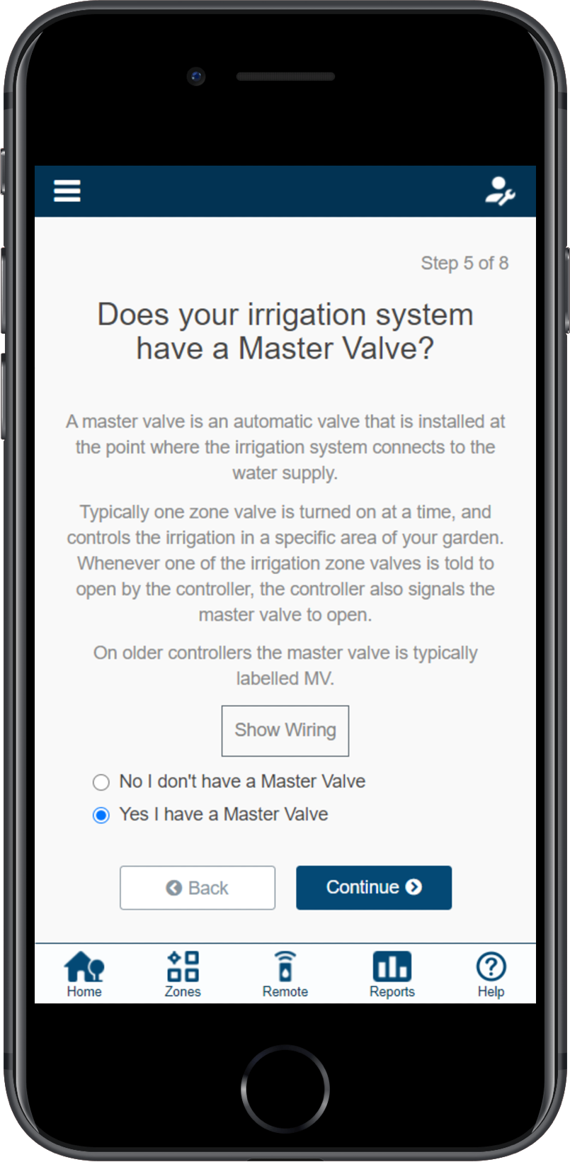
In the event, you need to change this in the software after the setup wizard, please refer to the instructions below.
- Sign in to your Hydrawise account
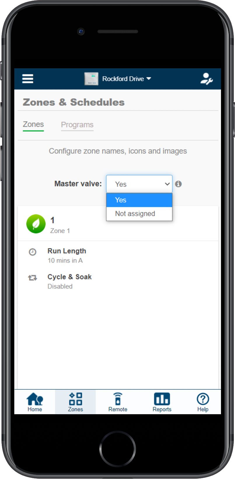
- Click on ZONES AND SCHEDULES for the PC or ZONES if using the mobile app.
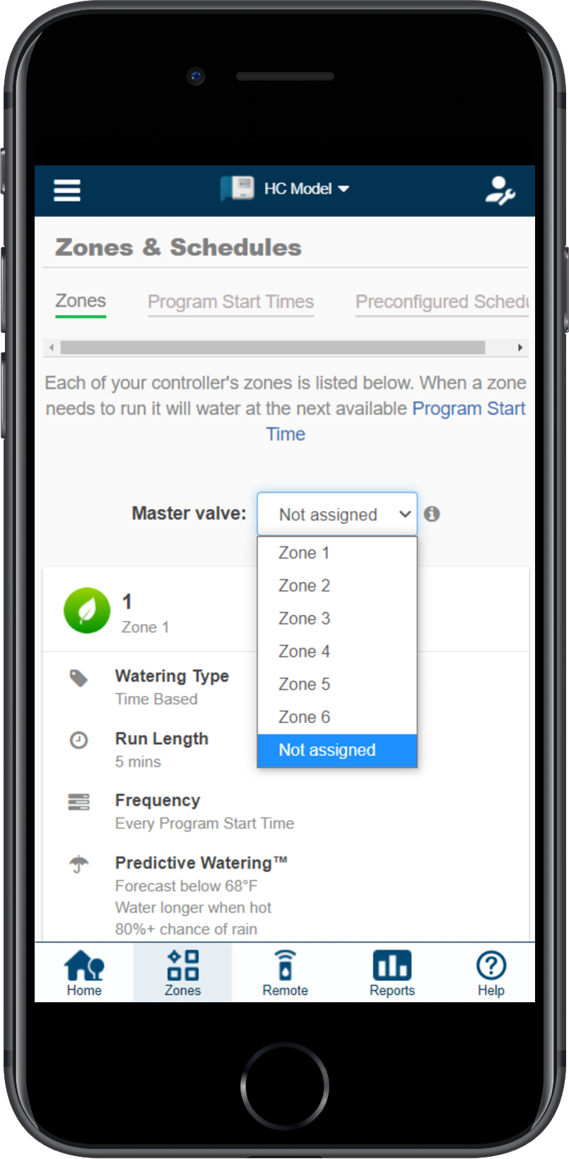
- Choose YES from the drop-down above the zones. If you have an HC controller, then you choose the zone number that you have the master valve wired to.
| HC Controller | X2 w/WAND, PRO-HC, HPC, and HCC Controllers |
 |
 |
| Master Valve (P/MV) Operation per Station |
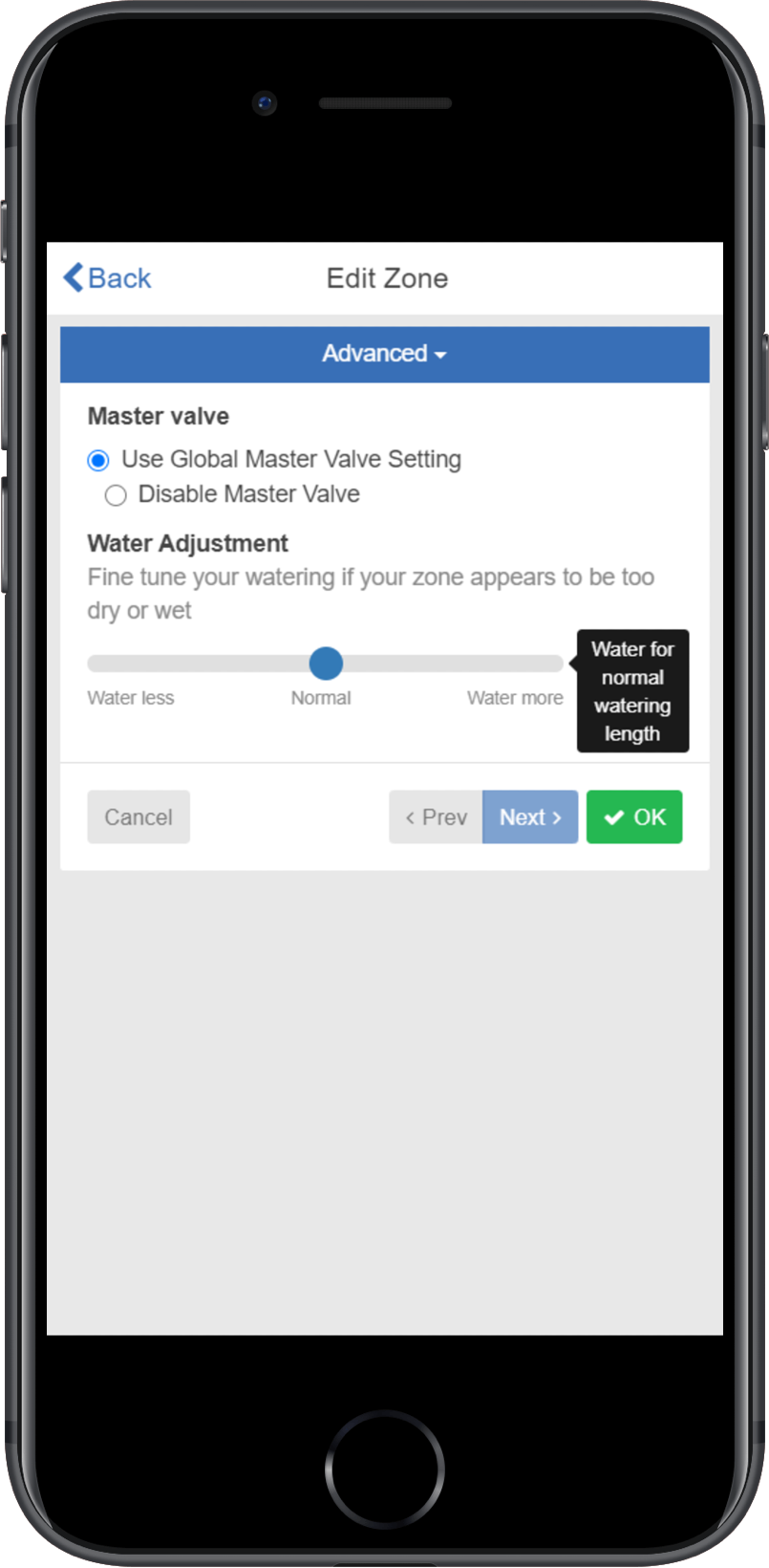
Selecting a master valve to be on/off for an individual zone, can be done when editing the zone in zones and schedules under advanced settings. This option is useful when one zone is using city water and another is using it from another source. This option is for X2 w/WAND, HPC, and HCC controllers only.
Please follow the steps below to change this setting.
- From the ZONES AND SCHEDULES page, click on the (
) icon on the zone you would like to edit.
- Click on ADVANCED located on the top blue search section.
- Select Use GLOBAL MASTER VALVE SETTING to keep this circuit on or select DISABLE MASTER VALVE to turn this circuit off.
Sprinklers Running with the Controller Off or Unplugged
There are two reasons why sprinklers would continue to run with the controller Off or Unplugged:
- It's possible your valves were opened manually. Locate your valve box(es) and turn the solenoid(s) clockwise until snug. The solenoid is located on top of the valve and looks like a cylinder with two wires protruding out of it.
- It's also possible that debris in the valve is causing the diaphragm to remain open.
To fix this problem:
- Disassemble the valve.
- Rinse all parts with clean water.
- Reassemble the valve.
If you cannot locate your valves, contact the contractor who installed the system.
| Cleaning the Diaphragm on a Hunter Valve |